Networking

Nov 262014
 

P1250310-1_resize

[CLICK ON IMAGES FOR LARGER VIEW] Completed a network / phone closet upgrade today. This involved several weeks of work adding around 20 new network and phone drops, removing the old PBX system, and extensive cable run cleanup. I really regret not taking a pic of the original condition but suffice it to say it was a mess! There is an extensive amount of spare / abandoned cabling still in place. I made sure to neatly stow this material out of the way but still make it visible for any future work. I also cleaned up the security camera cabling, added the Ubiquity wireless access point, and installed a professional-grade surge protector / outlet strip for existing and future equipment for this wall. These essential skills can be learned through ICT classes, providing valuable expertise for similar projects.

P1250315-1_resize P1250314-1_resize

Here is the way I use a 66-block to distribute 3 voice lines (with room to add a 4th without too much trouble). The feed from the other side of the building is in the lower left corner of the block. I then use a stripped Cat5 cable to daisy-chain the 4 pairs up and down the block with a pigtail coiled up at the bottom of the block. Now there’s room for a total of 11 drops to be fed from this single block. There are probably other solutions out there for doing a similar thing and for less time but when all you have is a block and some spare cable, this will absolutely work!

Aug 302014
 

Another small office network and phone setup. In this installation, I’m working with just 4 voice lines, a DSL / FAX line, and about a dozen network drops that will need to be installed (or retrofitted from existing cables)…

20140801_135110-1_resize
— Here’s the “BEFORE” configuration as it was when getting the voice and DSL installed from Verizon about a month ago. I have already tested most of the existing Ethernet cables hanging from the middle of the cabinet and most of them test good so I’m going to keep a good majority of them and run new bundles to some of the additional work areas in the remodeled office. I’m also going to re-use the 66-block terminals.

20140801_143741-1_resize
–I’ve setup the distribution 66-block for the 4 voice lines with a single 4-pair cable cascading down one side. I left enough slack at the end to continue up the opposite side or on a new block if the need arose.

P1220730_resize
And here’s the final result. I’ve added a simple shelf for the network switch, a surface-mounted box for testing all phone connections if needed, and ran all cables nice and neat.

P1220737_resize

One of these days I’m going to actually get to run cabling that is all of the same color!!

P1220752_resize

I ran the power cables with surface-mounted clamps like the rest of the cabling because the UPS still sits on a shelf that may get used for other purposes. I’d rather not have the power cable in the way!

P1220741_resize
–The feed from the pole comes from the 66-block on the left. I pulled the 4 voice lines in a single Cat5 cable to the distribution block to the right along with the DSL / FAX line on a single blue twisted pair. I like to have an outlet box at the network center point in the event that testing needs to be conducted.

P1220745_resize
–Here you can see the cascading distribution cable running below the grey cables that are going to the phone drops in the office.

P1220754_resize
–And here’s a closeup of the distribution cabling that I ran along the left side of the block.

P1220724_resize

Overall, there are a few things I would have liked to do differently. I would have preferred to start with new 66-blocks that weren’t already marked up. Then again, I can always get covers that will allow me to make notes about the line routing. With longer jumper cables, I would have liked to run them together in a single, clean bundle to the patch panel. Still, I’m happy with the end product and know this network will be easy to maintain and troubleshoot.

Aug 182014
 

Acton Before and After 01

This is a small real estate office in a rural town here in Southern California that was cabled and networked by a real amateur (at best). This company had fleeced by about 3 different IT companies over the last 10 years and I’m now there to clean up the mess. Here is the smaller project I recently completed.

bad-network-03
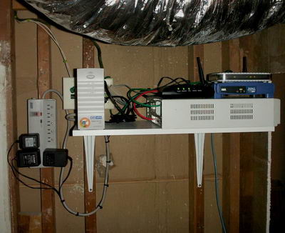
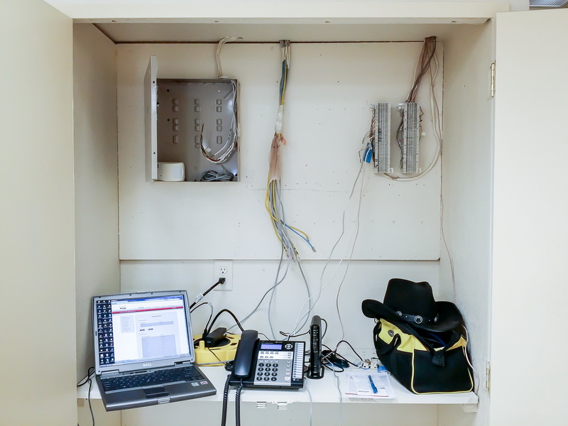
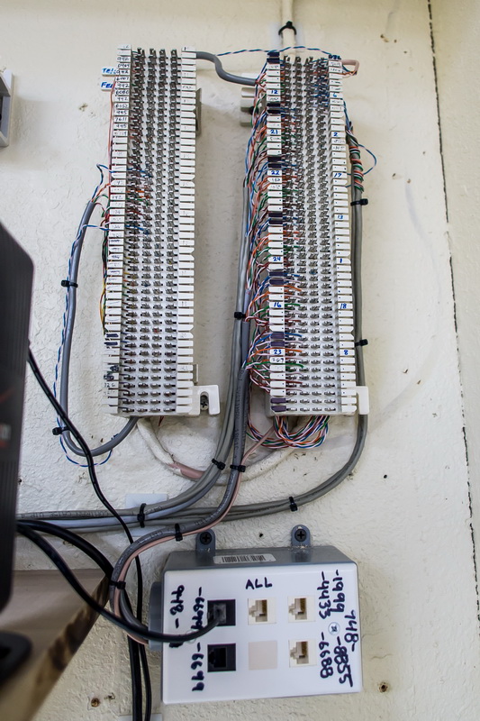
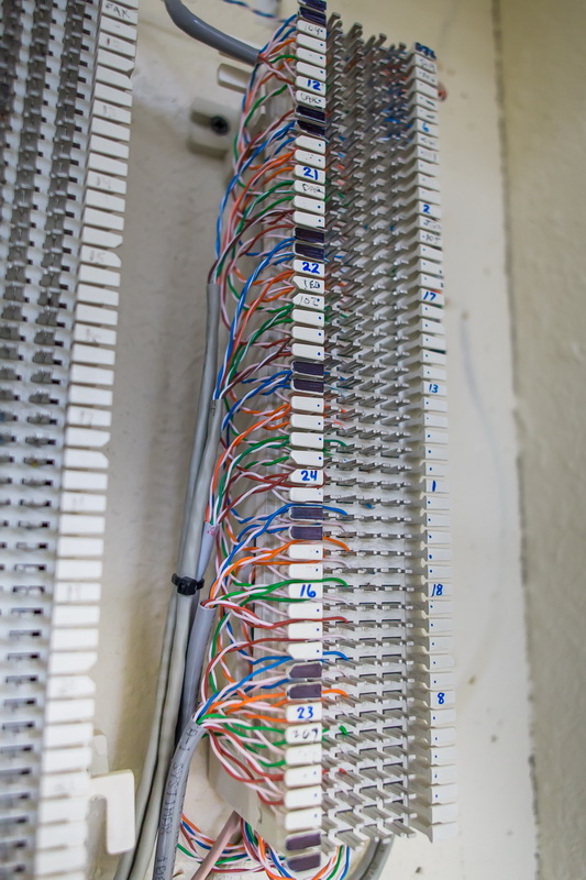
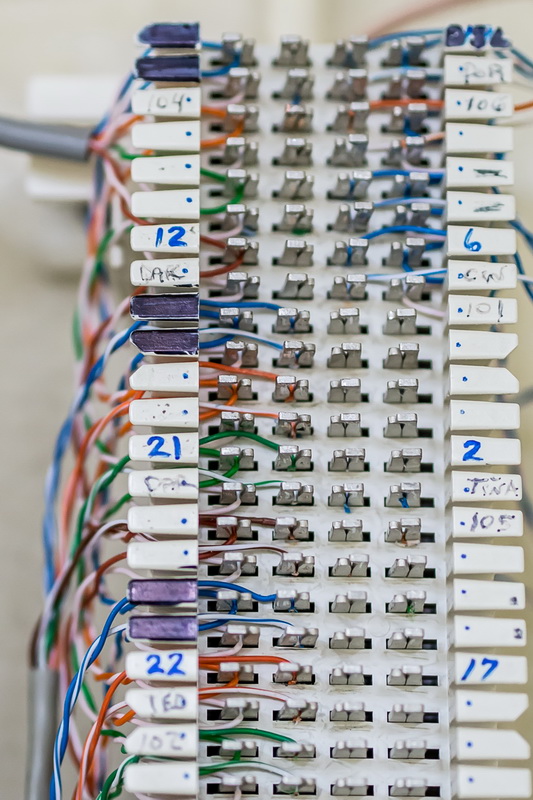
Above is the original condition of the network. This is the corner of the break room / kitchen in the office. There is legacy phone cabling on the wall (some of which is still in use), crap / trash on the floor, and a so-called business network running on unprotected outlet strips (not even surge protected). They run on the same circuit as the kitchen does so the blender, microwave, and refrigerator all affect the power to the network.

bad-network-04
You have to step on a 5 gallon paint bucket or a small ladder to get to the shelf where pile ‘o switches reside. About half of them aren’t in use…

bad-network-05
Next to that is a switch with POE running their VOIP phones. I already tested their network connection through the phone’s Ethernet out port and was able to surf just fine so there’s really no need for 2 separate network drops at each desk.

I did this in 2 phases as this office remodel so I first just needed to keep them running until I can pull all new cable to each office. First I installed a proper rackmount cabinet to safely and securely store all the equipment and patch panels (at a height that doesn’t require a paint bucket to reach). I installed a 1500VA UPS for power protection. Then relocated all the patch panels.

The 2nd phase was about 2 months later and entailed pulling all new cable so that there will be a clean and consistent run to this cabinet and not from about 3-4 holes in the wall at various locations.

** WORK BEGINS **

bad-network-09
–I’ve removed all the backboard that was previously mounted. In most cases, I didn’t even need to unscrew anything because it was only screwed into the drywall and didn’t hit any studs! Also, they used a lot of particle board and not plywood…

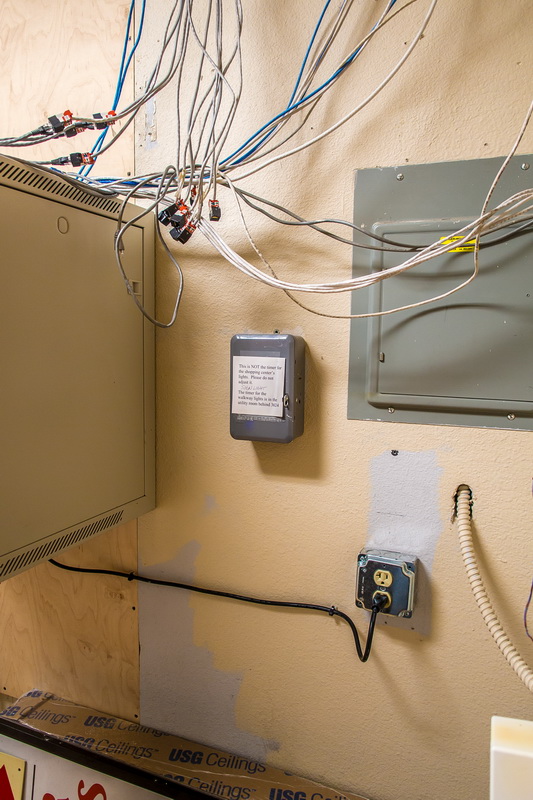
Next, I had my electrician install a new, dedicated circuit for the networking equipment just below the breaker box. By surface mounting the receptacle, I can run future conduit if needed for expansion.

My first issue was the 1″ deep pocket in the wall that needed to be even with the wall around the breaker box.

bad-network-10
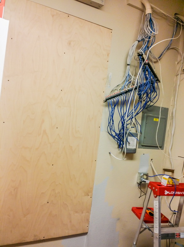
–Filled the gap with a sandwich of 1/4″ and 3/4″ plywood to make a total 1″ fill. Used deep screws to securely anchor this wood to the wall at each stud.

bad-network-11

bad-network-12
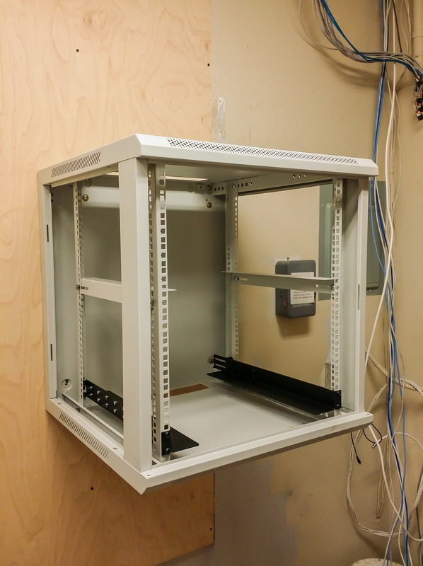
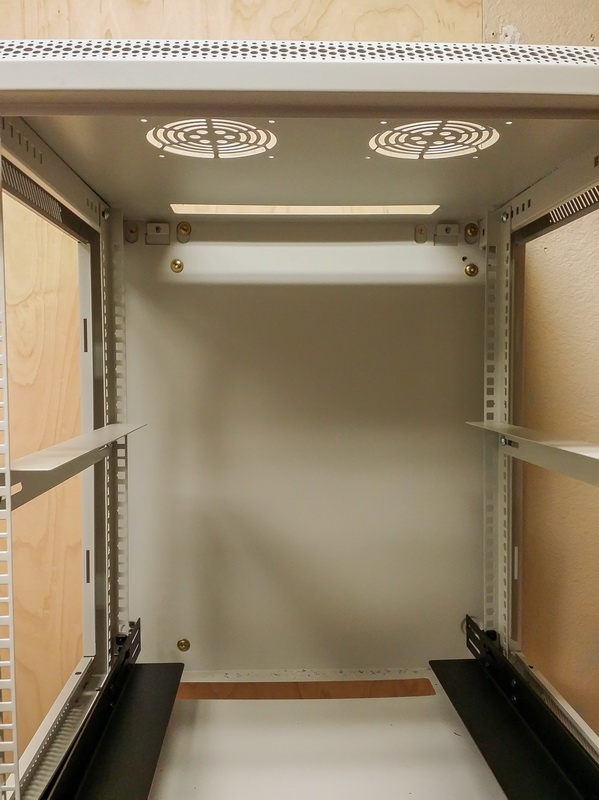
–Mounted a rackmount cabinet to the new plywood wall. I used lag bolts with very wide heads to spread the load and used 3 on each side in the corners of the cabinet.

bad-network-13
–Mounted a rail at the bottom and set a rather heavy 1500 VA APC UPS in place.

bad-network-14
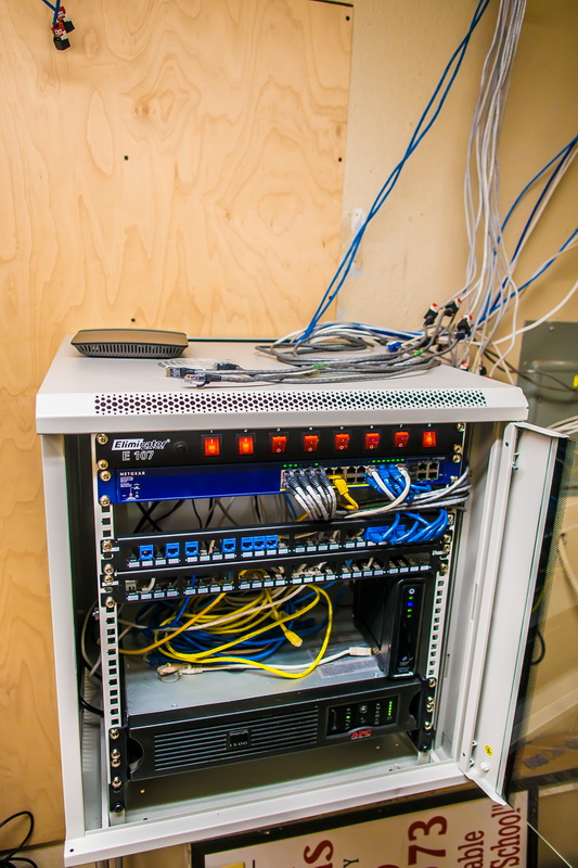
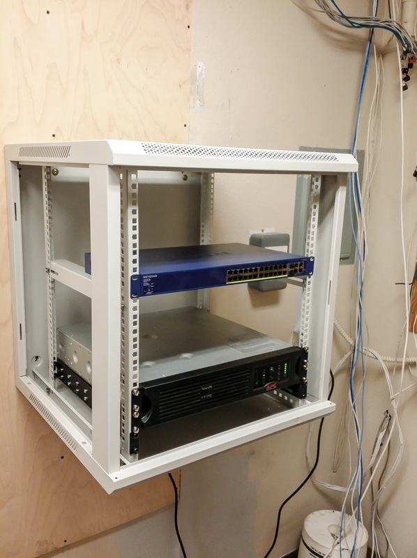
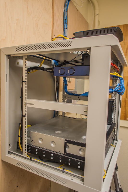
–Populated the cabinet with the current equipment needed to keep the office running until the remodel.

bad-network-15
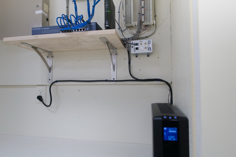
–Ran power to the cabinet in from the bottom opening and secured the cable to the wall.

bad-network-16
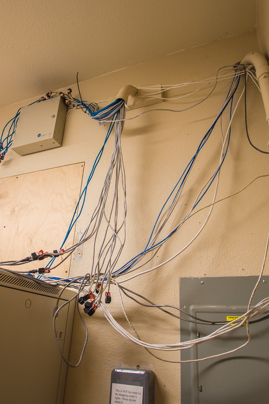
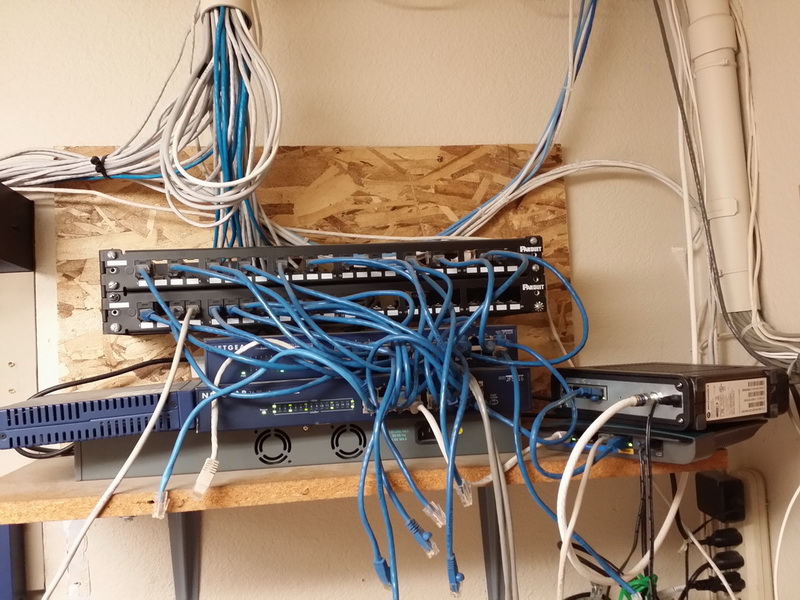
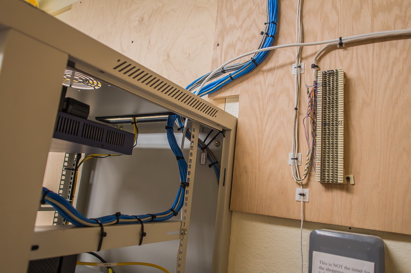
–I am running temporary jumpers that go out of the cabinet to reach the old cables for the moment. You can also see plenty of cables that aren’t being used now that their Internet connections for their PC’s are running through their VOIP phone jacks. Also, a majority of the office PC’s run wirelessly since they bring in their own laptops most of the time. You can also see the security alarm box that some moron decided to mount almost at the ceiling!

bad-network-17
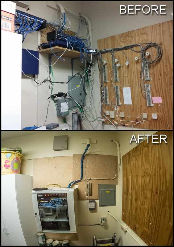
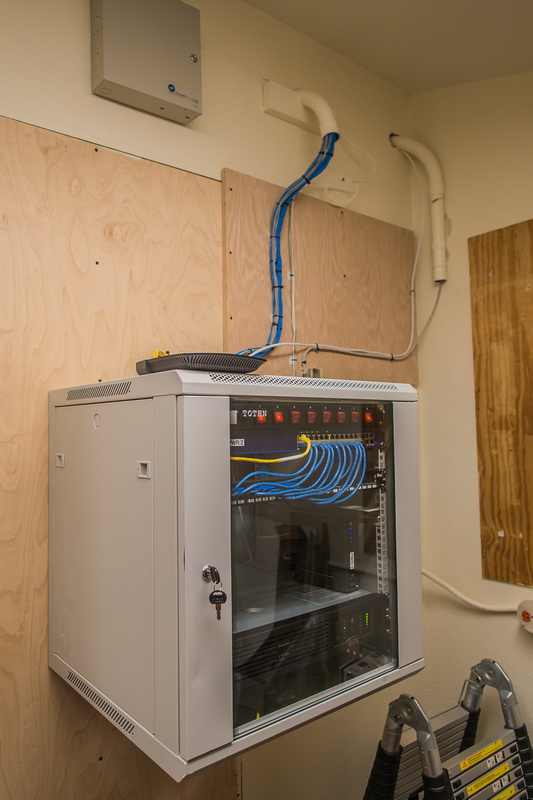
–So here’s the finished state in Phase 1. It was a 1-day (actually night) job I did over the weekend so there was no service interruption. Agents came in Monday morning and continued to work as normal. Still, even at this state, I feel much better about the network conditions. It is a much simpler configuration, easier to troubleshoot if the need arises, and there is a significant improvement in power protection.

** PHASE 2 COMPLETE **

bad-network-23
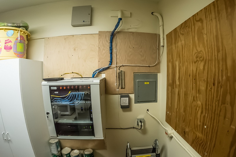
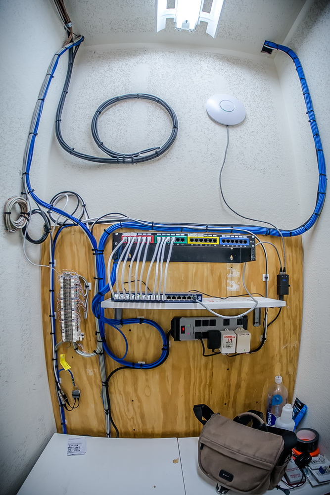
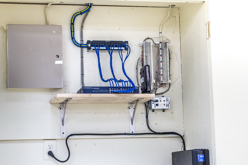
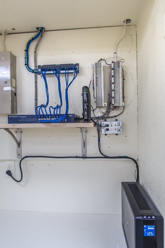
–Here is the completed setup. I’ve run all new cabling throughout the office, pulled all legacy abandoned phone cabling, and added a second backboard to the wall for future equipment.

bad-network-24
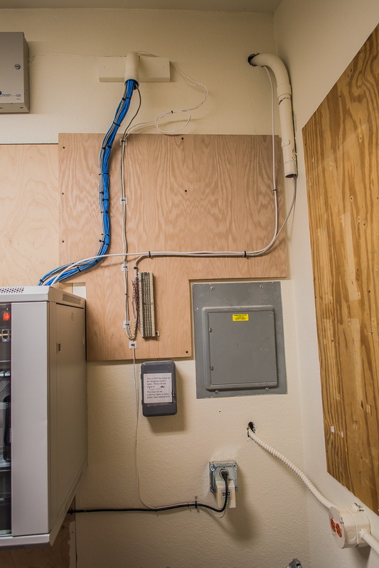
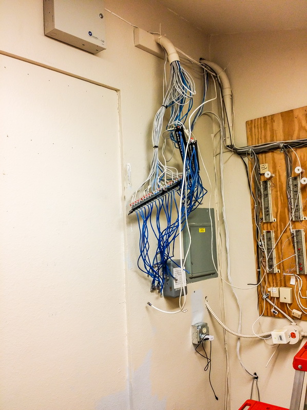
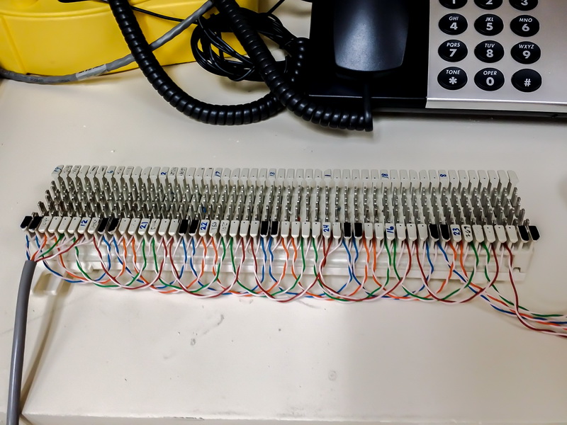
–With the additional backboard installed, I relocated the remaining 66-block that runs just a single analog FAX line (soon to be replaced with a virtual FAX line) and the alarm system. I also relocated the alarm system power to the new receptacle. I will probably be adding a second receptacle to this wall with an independent circuit just for the pending T1 and related equipment that will be installed. Until then, we’ll make due with what’s here. If the alarm company wants to relocate their box to a more reasonable level, they can now as well!

bad-network-21
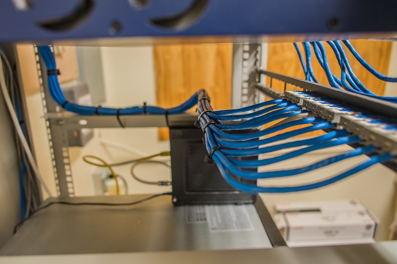
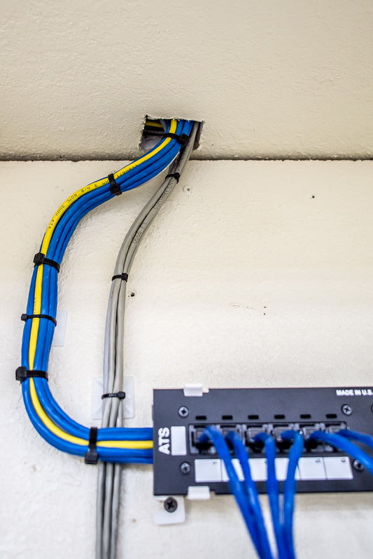
–I ran double the amount of CAT5e cable as was needed but had no need to terminate them all. So I split the spare cables to a separate bundle and labeled them as spares in the back of the cabinet. This turned out to be a good thing as the company decided they wanted to re-activate their analog FAX line (which I wasn’t expecting to do) so I was able to use one of my spare cables. Additionally, one of my lines must have been damaged during the remodel and I was forced to use the second cable run to one of the network drops (That’s why there is still one grey cable in the bundle running to the patch panel -I was hoping to keep them all blue).

bad-network-20

bad-network-18
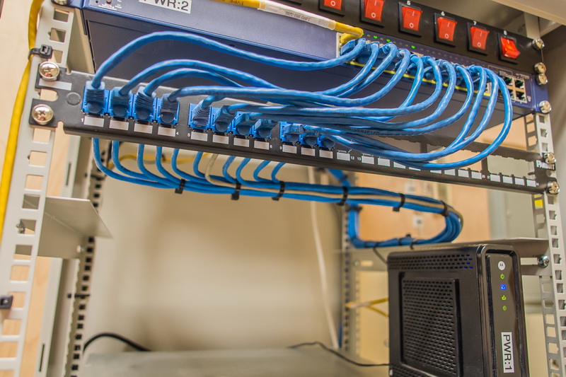
I wasn’t able to obtain a bar to run behind the patch panel so I had to rely on the strength of the cables to maintain the form after I had them terminated. I like to leave a good 3-4 inches of straight cable behind the patch panel in the event of troubleshooting or repairs in the future.

bad-network-19
–Dressed all the power and data cables around the frame of the cabinet before closing the doors.

bad-network-25
–All finished and closed up! After terminating all active cables, I dressed the cable bundles back up to the ceiling and into the space above the suspended ceiling, you can also contact professional from Suspended ceiling London to ensure the safety on your ceiling. This means I still have a good 6-10 feet of slack on each cable I’ve run (including my spares). If there is a future change that needs to relocate this panel, I have a large amount of slack to pull from overhead. I like adding the switch panel at the top of the rack to allow power cycling of equipment when troubleshooting. This means no one is reaching back behind equipment to pull power cables. I’ve clearly labeled on each piece of equipment what number they’ve been assigned on the panel as well as a master list on the switch panel itself. Not a bad addition for a relatively low cost!

Future plans involve adding a T1 and all new VOIP phones and a Cisco router / switch to manage the system. At that time, I will install a dedicated WAP to replace the consumer-grade wireless router sitting on the top of the cabinet!

I’m pleased with the result. This is now a secure and reliable network that will be easy to upgrade, troubleshoot, or modify.

Jun 282011
 

Working at the phone company has brought me back to my roots as a wiring technician on the B-2 Stealth Bomber nearly 20 years earlier. In recent years, the phone company has determined that using plastic zip-ties just doesn’t have the longevity that wax string does so from now on any new work with their equipment gets “12-cord” wax string to tie down cabling. Now fiber optic cables that attach to metal require an additional form of chafe protection which is provided with the “fish tape” material shown in these photos. I have spent the good portion of the last week slowly working my skill up in the cable-stitching art to make it not only secure but neat and clean. This particular cabinet you see here on the left holds a number of fiber distribution panels (FDP’s) and then attach themselves to these large cables out the back that are routed to an underground cable vault to be spliced into the cables running out to the customers in the surrounding area. These cables carry up to 144 individual fibers inside so it is very important that they be secure and protected!


Here you can see a shot of some of the stitching inside the FDP rack cabinet. This particular stitch is called a “Chicago” stitch. What made this job particularly difficult was having to work around the bracket that is in place to protect the cables.


In this shot from below you can see more of the Chicago stitch and how it holds the cables down and keeps them individually separated.


Apr 192011
 

Well it’s been over a month now at my new job and I’m still loving it!! I can’t thank Gerry Hernandez enough for the opportunity this is to me –this is by far one of the greatest things anyone has ever done for me. I have blown so many great career opportunities in the past –and now I’m actually glad because it brought me here to the phone company! I get to play around with some of the coolest pieces of equipment, run cables, test equipment, and generally NOT sit at a desk all day. Here’s a shot of me in the Lancaster central office with the “mainframe” behind me. That’s pretty much all of central Lancaster phone lines winding up where I work. How cool is that?! Anyways, I think this is the perfect blend of mental and physical work for me. Maybe I’ll finally lose that weight I first gained 15 years back when I first got a desk job…

The shot on the right I took at a local cell site. Behind me are the transmitters.

Sep 162010
 

–click on the image for a larger view–

Well I finally ran into a situation where I needed to implement the so-called “triple router Y-configuration”. There are several pages that talk about it but the one that I got the information from Steve Gibson and Leo Lapporte’s podcst of Security Now. You can find a transcript of the episode here. There is another page that describes it with a few good illustrations here.

The situation was one where a medical office needed to provide internet access for a workstation but with complete isolation from the current production network in place. The solution is either to lease a new DSL line just for this one machine, or find another way to isolate two networks and still share a single Internet connection. This is a much more economical solution! Normally, the Y-configuration is used in situations where someone needs to provide wireless access to devices that aren’t able to employ WPA encryption. The Nintendo DS is one example of a device that either uses open Wi-Fi or WEP encryption only. Many security-conscious network operators wanted to find a way to provide an economical dual-network setup with a guaranteed isolation between each network. As Steve Gibson so thoroughly explained, only a triple router Y-configuration will work.

The only aspect of this setup that turned out to be a problem was the fact that this office was using Windows Remote Desktop services which involved port forwarding. I tried a few possible solutions to keep that working but simply wasn’t able. Frankly, it was time to move past RDP and to a more secure solution so I’m not too upset about it!

Sep 162010
 

–click on the image for a larger view–

Another job I did for a church about a year ago. I just wish I had snapped a shot of the “before” condition! I added the plywood at the top, re-routed all the coax components to a more clean-running setup (and made room for the new parts). I cleaned up all the phone line cabling to the punch-down block and labeled all the current working phone lines, added a modem, router, and gigabit switch. I also installed 2 wireless access points around the building… This actually was a pretty fun job.

You may notice the additional network patch panel at the top right and the cable modem at the bottom right. This was to accommodate a charter school that was making use of our facilities temporarily. They’re no longer at this building but some of their parts are still in place.

Sep 162010
 

–click on the image for a larger view–

Just finished another home networking job for a client. Nothing too fancy but I did manage to clean up the “fire hazard” wiring that was running over the floor of their covered patio room (that occasionally would flood when it rained). Now all the equipment is tucked neatly away in a small cabinet at arm’s reach for easy access and maintenance if needed. I ran networking from here to 2 drops within the property as well as phone lines to the feed from the pole and another building on the site. Now all equipment is surge-protected and out of the way. Not too bad for a one-day job!

May 122010
 

–click on the image for a larger view–

So I’m remodeling my house. Yeah, I know it’s been several years –and it will probably be a few more before I’m done. Hell, I’m hoping to get it all done before I die at this point! But in the mean time, work has to get done so I’m now working out in the living room adjacent to Candi’s make-shift nail salon. I will say it’s nice to be working together (even if we’re working on totally different stuff at the same time…

Continue reading »

Jul 092009
 

–click on the image for a larger view–

I’m such a dork! I used to laugh at those little school girls that would go all crazy for the Jonas Brothers when they saw them –but I’m just the same way! I’m reminded of a great Intel Commercial when I ran into the opportunity to personally meet Steve Gibson of Gibson Research Corporation, the man who coined the term spyware and created the first anti-spyware program, creator of Spinrite and ShieldsUP while I was in Long Beach a few weeks ago. I knew that he had mentioned on his weekly Security Now podcast that he’s been doing most of his coding work while sitting in a Starbucks at UCIrvine. Well that was just a quick 20 min drive for me! Steve was most gracious to me and we talked for a short while as I tried to keep from jumping up and down shouting “I can’t believe I’m actually talking to THE Steve Gibson!!!” Anyways, thank you Steve for being so accessible and contributing so much of your time to the computer security industry.

Oddly enough, I’m not the only one with this attitude… SecureShirts.com even makes a nice black T-shirt that shares my sentiment…

–click on the image for a larger view–

He’s also #66 in TechCult’s Top 100 Web Celebrities.

Jan 142007


My home network has been going through an “evolution” over the past few months as a result of continued outages and “growing pains” but I think I’m finally done changing configurations and running wires for at least the next few months. For those of you interested, I’ve posted pics below…
Continue reading »