Technical Illustration


I have been doing technical illustration from the very beginning of my CAD career in 1995. Creating illustrations to convey complex systems and mechanisms is a real talent of mine. I have used anything from mainframe CAD platforms within the aerospace industry to the very basic of digital tools to get my work done. I have used Adobe Illustrator and Photoshop but prefer to use Gimp these days for simple 2D illustrations. For 3D illustrations, I’ve used Chief Architect, Google SketchUp, as well as Autodesk’s AutoCAD. Below are some samples of my work throughout the years.
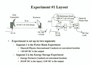
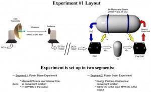
**BEFORE** –click for larger image– Design Flow Diagram Here I was given an existing flow diagram as created by the original design engineer. The issue at hand was the fact that this design needed to be presented to investors that had a less technical background. There was a need to create the same illustration / diagram in a more “flashy” way. So I created 3D renderings of the various objects and use more artistic arrows and related elements. **AFTER** –click for larger image–

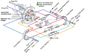
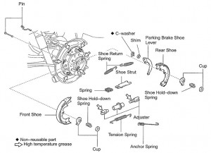
**BEFORE** –click for larger image– Exploded View Diagram / Assembly This is an example of taking and existing technical illustration and actually making it useful! It began with the need to update a rear drum brake assembly found on an import SUV I was working on. I started with the original factory illustration for an exploded view of the assembly. The problems were many: inefficient use of the space, unclear or no connection paths, improperly or missing part designations, etc. I decided to rework the entire illustration using Gimp graphic software to do the work. This allowed me to work in multiple layers so I could overlap items without the risk of damaging the underlying graphic elements. I’ve have since used this illustration to publish a working document for future work by other mechanics needing to perform the same operation. **AFTER** –click for larger image–